Chuck Dunbar's
Whirligig Design and Development
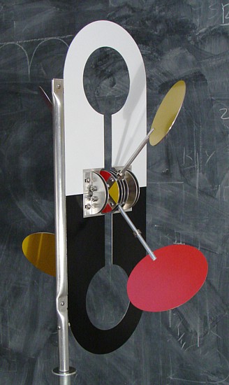
Whirligig #57
Complete Plans SOLD
_______________________________________________________________________________________
Use Google translate
Utilisez Google Translate
Utilizar Google Translate
Utilizza Google Translate
Mit Google Translate
Uzyj Google Translate
Use o Google Translate
_______________________________________________________________________________________
Chuck Dunbar's
Whirligig Design and Development
Whirligig #57
Materials list

_______________________________________________________________________________________
Chuck Dunbar's
Whirligig Design and Development
Whirligig #57
Special tools
_______________________________________________________________________________________
Chuck Dunbar's
Whirligig Design and Development
Whirligig #57
Read the directions through before starting.
Note on Drilling Holes Accurately
Increasing the accuracy of drilled hole placement is very simply. Twist drills do not come to a point. They come to a chisel edge. [http://www.mfg.mtu.edu/marc/primers/drilling/nomen.html] If used on an smooth surface they wander. Take time to use these steps to prevent drill wander.
Whirligig Design and Development
Whirligig #57
Complete Plans SOLD

Use Google translate
Utilisez Google Translate
Utilizar Google Translate
Utilizza Google Translate
Mit Google Translate
Uzyj Google Translate
Use o Google Translate
_______________________________________________________________________________________
Chuck Dunbar's
Whirligig Design and Development
Whirligig #57
Materials list

_______________________________________________________________________________________
Chuck Dunbar's
Whirligig Design and Development
Whirligig #57
Special tools
- 9 " Band saw with a 1/8" blade to cut non ferrous metals
- Table saw to make blade jig and circle jig
- General wheel and circle cutter, part #06
- Vise with about a 5” jaw or bending break
- Inexpensive micrometer
_______________________________________________________________________________________
Chuck Dunbar's
Whirligig Design and Development
Whirligig #57
Read the directions through before starting.
Note on Drilling Holes Accurately
Increasing the accuracy of drilled hole placement is very simply. Twist drills do not come to a point. They come to a chisel edge. [http://www.mfg.mtu.edu/marc/primers/drilling/nomen.html] If used on an smooth surface they wander. Take time to use these steps to prevent drill wander.
- Use a sharp punch (I use an ice pick.) to mark the hole location. Use a very small drill, 1/16” or 5/64’ diameter, to drill a pilot hole at the punch mark.
- Look closely at the drill bit’s chisel edge. The chisel edge should be shorter than the diameter of the pilot hole. The chisel edge should fit into the pilot hole. A 5/64” diameter pilot hole will accommodate drills up to ¼” in diameter. For larger holes, drill a second pilot hole with a diameter to receive the larger drill’s chisel edge.
_______________________________________________________________________________________
Chuck Dunbar's
Whirligig Design & Development
Whirligig # 57
Vane

 |
| Click on image to enlarge |
- Cut two pieces of aluminum sheet 8” x 10 ¼”.
- Completely lay out the identical vanes on the aluminum rectangles. Do the same operations on each part of the vanes at the same time. Mark the hole locations with a punch. Do not use a hammer. The blow will deform the aluminum.
- Drill all the holes, except the blade opening.
- To cut the round at the end of the aluminum sheet and the blade hole, you will need a circle jig. Usually the jig has a small nail to center the work at the desired radius. (Photo1])
- Where the vane centerline crosses the 6 ½“ dimension, drill a pilot hole just big enough to accommodate the nail in your band saw circle cutting jig. Cut the outside circle first. Be careful not to cut through the other shapes of the vane.
- Cut the inside circle for the blade opening. When you are about half way around the circle, put masking tape over the band saw blade kerf to hold the vane in correct position. (Photo 2)
- Cut the two inside edges up to the inner circle to make the opening for the blade arms. Make the long cut up to the tab, which fits into the mast. Use a fence or sliding table on the band saw.
- Make the remaining small cuts to reveal the shapes.
 | ||||
| Photo 1 |
 |
| Photo 2 |
_______________________________________________________________________________________
Chuck Dunbar's
Whirligig Design & Development
Whirligig # 57
Hub
 |
| Click on image to enlarge |
- Lay out the four hub disks on a single piece of aluminum. For future reference scratch the two axes into the metal . Mark the hole locations with a punch. Do not use a hammer. The blow will deform the aluminum.
- Drill a pilot hole for the General Circle cutter.
- Cut the four disks. Make certain that the work is firmly clamped in place.
- Remove burrs from the disks. Stack the disks facing the same way. Tape them with masking tape. (photo 3)
- To make the jig, in a piece of scrap wood drill a ¼” diameter hole through. Put a short ¼” diameter bolt through the wood and disks from the bottom. Tighten the nut to hold the disks in place.
- Drill pilot holes for the 3/16” holes. Once the first 3/16” diameter hole is drilled through the metal disks and into the wood, put a short length of 3/16” tube or rod through the disks and into the hole. This will keep the disks aligned.
- Repeat the procedure of step 6 for the opposite hole. (photo 4)
- Drill the remaining 3/16” holes.
- Keep the disks taped together and put them into a vise and mark the edges diagonally with a file. (photo 5) This will allow for the disks to be restacked in order, an advantage if the hole locations are slightly off.
 | ||
| Photo 3 |
 | ||||
| Photo 4 |
 |
| Photo 5 |
Chuck Dunbar's
Whirligig Design & Development
Whirligig # 57
Whirligig Design & Development
Whirligig # 57
Hub Parts
- Cut the spacers for the hub with a jig setup on the band saw. Finish to .250” +/- .002”. It is not very difficult to achieve the required precision with ordinary tools - band saw and sandpaper. A micrometer is useful.
- File the two flats into the axle.
- Cut the two axle sleeves.
 |
| Click on image to enlarge |
_______________________________________________________________________________________
Chuck Dunbar's
Whirligig Design & Development
Whirligig # 57
Whirligig Design & Development
Whirligig # 57
Bearing Brackets
 |
| Click on image to enlarge |
 |
| Click on image to enlarge |
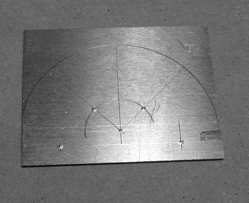
- The order of fabrication is important. Layout the 8 brackets on a single piece of aluminum, two rows of 4. Make each rectangle 2 1/8“ x 2 5/8“. Scribe the lines for reference later. (Photo 6)
- Drill pilot holes, then drill the four 3/16” diameter holes. Remove burrs.
- On the band saw circle, cut a 1 ¼” semicircle. Clamp all 8 pieces together and smooth edges with a file and sandpaper. (photos 7 & 8)
- Clamp the piece. Drill a second ¼” pilot hole. Then drill the 7/16” diameter hole. (photo 9)
- Cut the slot to 7/16” diameter hole. (photo 8170)
- In a vise or small bending break, make the bend a 91 degree.
- Cut the remaining two slots and finish like the larger slot.
 | |
| Photo 6 |
 |
| Photo 7 |
 |
| Photo 8 |
 |
| Photo 9 |
_______________________________________________________________________________________
Whirligig Design & Development
Whirligig # 57
Blades
 |
| Click on image to enlarge |
- Lay out the blade pattern on heavy paper. Construct an oval with the axes dimensions shown. Using a French curve to draw the elliptically shaped blades gives a close approximation. Transfer the shape to the sheet metal. On the metal, scribe the perpendicular centerlines. They will be useful later when attaching the blade to the arm. (If you have a computer, check your photo editing software. There may be an editing tool that allows you to choose from among different shapes. One may be an oval whose dimension you can set and print out full scale.) (An oval of this dimension set a 45 degrees from the plane of rotation appears to be a circle in the foreshortened view from the front or side of the whirligig. This adds some visual interest.)
- Cut the oval on the band saw.
- Tape the blades together matching the axes lines.
- Put them into a vise. With a file and sandpaper smooth the blade edges to get to get a well shaped oval.
_______________________________________________________________________________________
Chuck Dunbar's
Whirligig Design & Development
Whirligig # 57
Whirligig Design & Development
Whirligig # 57
Blade Arms
 |
| Click on image to enlarge |


- Make the hub end first. Put the arm in a vise. File the first flat. (photo 10)
- Put a piece of wood the same thickness as the arm, ¼” in the vise. Rest the first flat against the plywood. File the second flat. (photo11) Use a micrometer to check the distance between the flats.
- Mark the hole locations and drill 9/64” pilot holes. (photo12)
- Make the blade-arm jig from scrap wood. The 45 degree slot should be a tight fit to the hub end of the arm. Cut the blade slot first on the band saw using the jig. With the arm in a vise widen the slot first with a hacksaw, then progressively widen the slot to .05” with sandpaper.
- Put the arm back in the blade-arm jig. Insert the blade in the slot using the scribed lines to orient the blade correctly. Tape everything down. Drill the first hole in the arm with the blade in place. (photo 13). Put in the first rivet to hold things in place. Drill the second hole. (photo14)
- After inserting the second rivet, put the assembly in a vise. Carefully and slowly tighten the vise to crush the rivets. (photos 15) The rivets hold very well. Grind or sand them flush.
 |
| Photo 10 |
 |
| Photo 11 |
 |
| Photo 12 |
 |
| Photo 13 |
 |
| Photo 14 |
 |
| Photo 15 |
_______________________________________________________________________________________
Chuck Dunbar's
Whirligig Design & Development
Whirligig # 57
Whirligig Design & Development
Whirligig # 57
Mast
- The jaws on my vise are ¾” deep, so I have made the parts of the mast that hold the tabs of the vane ¾” too. Improvise or get new jaws if yours are not ¾” deep. After cutting the mast to length, crush the tube at the dimensions indicated.
- After crushing the mast, use a hacksaw to cut into one side of the fold about an 1/8“. (photo 16)
- Tidy up the cut with a file. (photo17 &18)
- Check to make sure tabs fit. Either crush the mast more or pry open the slot more to give a snug fit with the tab.
- Check the hole locations against the hole location in the tabs on the vane. Drill the holes. With the vane tabs fastened to the vane, check to make sure the two halves of the vane meet.
- Drill a through hole for securing the mast plug.
 |
| Click on image to enlarge |
 |
| Click on image to enlarge |
 |
| Photo 16 |
 | ||
| Photo 17 |
 | ||
| Photo 18 |
_______________________________________________________________________________________
Chuck Dunbar's
Whirligig Design & Development
Whirligig # 57
Whirligig Design & Development
Whirligig # 57
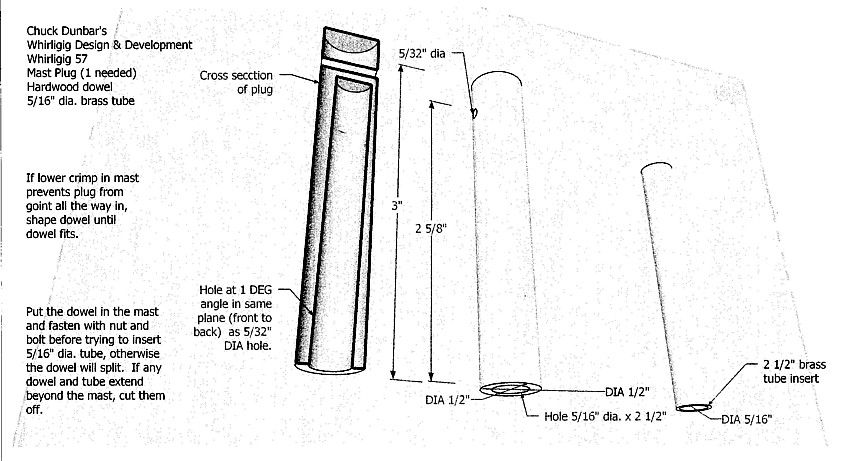
Mast Plug
- Cut the hardwood dowel to length, and drill the 5/32” diameter hole.
- Set up a jig to drill the hole the length of the dowel plug. (With a paddle bit, drill a ½” diameter hole at 1 degree slant into short length of board. Secure the board to the drill press table and insert the plug in the jib hole.) If necessary finish the hole with a hand held electric drill. The purpose of the slant is to account for looseness in the fit of the stand’s pintle in the metal socket of the plug. The whirligig does not look good if it leans back. It looks much better if it is straight up or leans slightly forward.
- Put the plug in the mast. Align the hole in the plug with the hole in the mast and insert a 6-32 x 1” machine screw through the holes, screw head to the front. Cut the screw even with the nut to avoid conflict with the vane. Insert the brass 5/16” diameter brass tube into the dowel. A little soap rubbed on the brass tube will help lubricate it.
 | |
| Click on image to enlarge |